Leaderboard


Popular Content
Showing content with the highest reputation since 12/10/04 in Posts
-
Don't tell my wife Like I tell other people. some like to fish, some like to bowl, I like to make.8 points
-
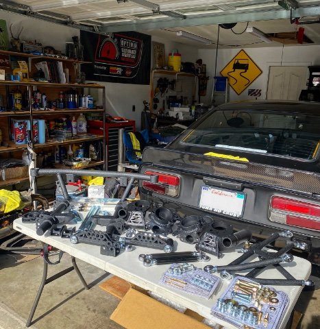
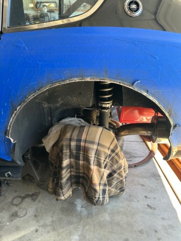
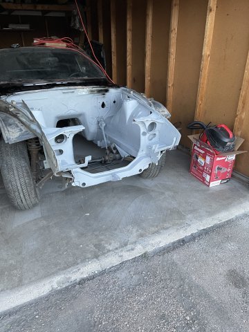
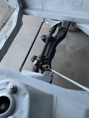
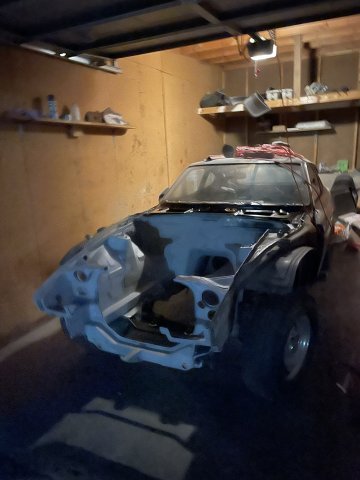
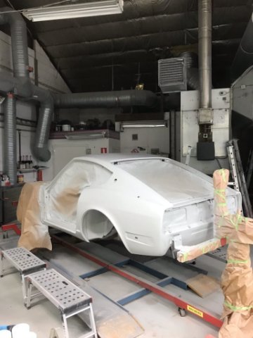
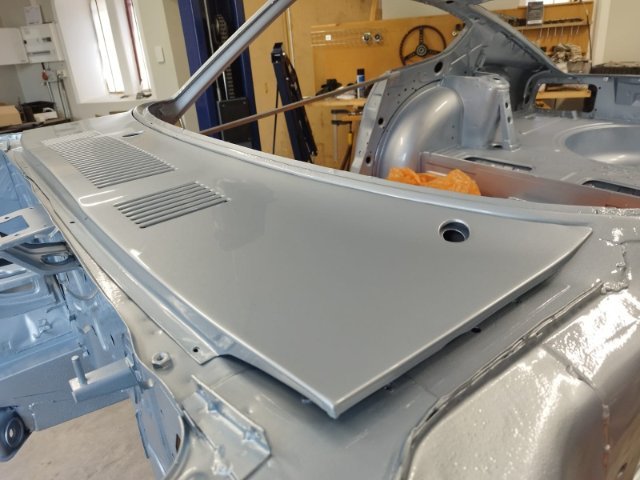
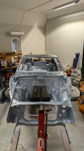
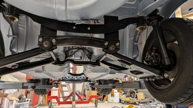
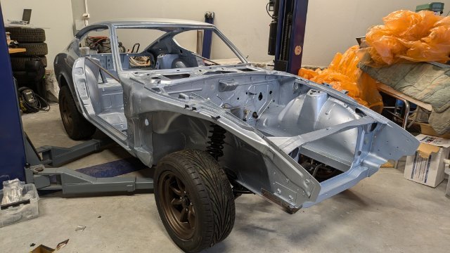
3 years later... took ages to find a good painter willing to take on the project. These days insurance jobs with small panel fixes seem to be more profitable. Luckily I found someone willing to do it in the summer months of this year while the insurance workload is reduced. Prepping... Overall quite happy with the result. Couldn't contain myself and started puzzling together the undercarriage the first chance I got. Pulled lines in the trans tunnel and assembled the suspension component. On the wheel first the first time since 2017!
 6 points
 -
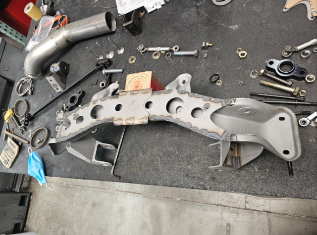
More pis of it finished up The bottom plate was beat up a bit and bent from floor jacks. So I took off the old one by drilling out the spot welds. I then drew up the shape and had a new one laser cut. The center plate that is welded to this plate, I re-made it as well, but out of 304 stainless steel. This way I can leave it a brushed stainless finish after powder coating and it is a good place to use a floor jack. I then spot welded on the larger plate in the original locations I then tigged the seam between the spot welds Then tigged on the center stainless plate Then blasted the entire cross member and powder coated it in a super black semi gloss powder coat. Powder coated the motor mounts as well I always first do a primer powder coat that is sandable I sand most off this off to fill the small blemeshes Then final coat Finally the brushed stainless plate for the floor jack Next up is getting a new transmission, then finishing the exhaust
6 points
-
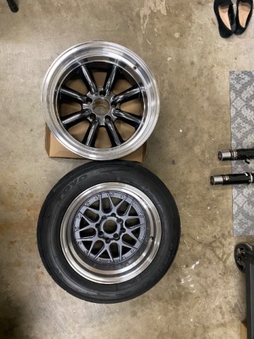
Been a while since I posted any updates. Been moving along. For the Turbo car I decided to build my own wheels. Ill CNC machine the center sections myself and have the lips and barrels spun for me. I really like the old SSR RS8 wheels but finding them in the correct bolt pattern, offset, and caliper clearance is impossible. I fould a set close, from Japan and had them shipped over. Since this car uses Z31 hubs and such, the spacing is out much more than a standard Z so I need a bit more positive offset. I dissasembled the wheels and scanned the center section into my computer and reverse engineered the shape. Next I re-assembled them and had the 245-45-16 tires Im going to use mounted. I test fitted them to the car, and close, but not good enough. This is the fist time this chassis has been rolling on its own wheels in 27 years. Its been on a cart or a lift. Felt good to see some progress now that the suspension, brakes, and cross-memeber are finally complete Scanned this complete assembly and put it in CAD. Now I have the exact shape of the tire on the rim. Cool cross section of it. Finally I scanned the side of the car, put it into CAD. Now I can adjust my wheel center offset for caliper clearance, and adjust it to work with new Lips and Barrels I will order for the proper offset and fit to the car. Having it in CAD alowed me to look at it from every angle and check all clearances, for calipers, springs wheels lip, ect. Even compressing the suspension to make sure I have fender clearance at full travel Final wheel spec is: Rear - 5 lug = 245-45-16 on 8.5" width rim- 27mm positive offset, 2.25" outer lip on the rim Front - 5 lug = 245-45-16 on 8.5" width rim - 31mm positive offset 1.75" outer lip on the rim Next I need to find some time to program the CNC and start cutting chips. But I got distracted on the NA car, so that update is next.
5 points
-
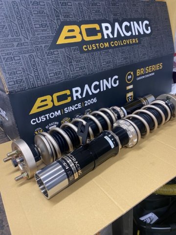
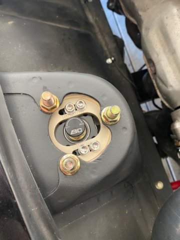
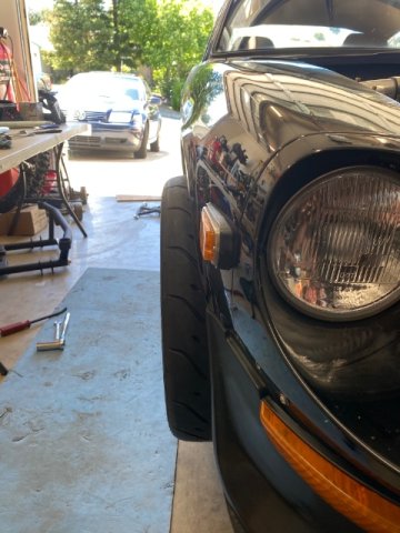
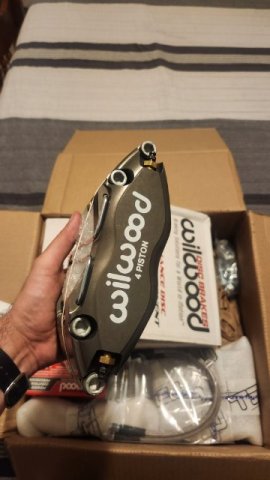
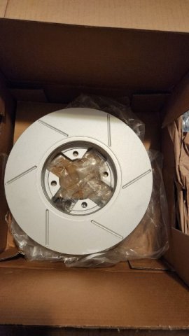
Three weeks until I'm home and properly working on the car before a long road trip. I've been creating a detailed list on some Google notes of everything I hope to accomplish. I'll update once I truly get to it, but for now just wanted to share my excitement for my new brakes. Was in Utah about two weeks ago for a handful of days for a music conference and my brother was kind enough to let me borrow his truck to drive up to Logan just for one evening to have a quick dinner with the siblings up there and I took a quick trip to my folks' place late in the evening and opened up some of the parts to keep my motivation haha. Also had a big box of new seals from Resurrected Classics. They were kind enough to give me a steep discount on their weatherstripping kit when I asked if I could get it without the door seals since I had already purchased the S30 world seals before they released their kit. Looks like they were kind enough to give me the discount and kept the door seals anyway! I'll be making a thorough comparison of it against the Precision kit I have, mostly to see if it's truly far better for some of the worst fitting parts.
5 points
-
I have two heads in stock as I type this so the head can actually be purchased. I can't help that you can't afford it. That's a feature not a bug. For the very beginning my goal was to provide the components so that talented engine builders could make the decisions on the types of components they wanted to use. Based on what I've seen and taking the pricing of the relatively simple L6 head as the baseline I highly doubt it. I'm not really sure what I did to put a burr under your saddle but you remind me of the guy that starts a fight in the line to get into the club because he can't afford the cover charge. Just get out of line and go somewhere else.5 points
-
He's saying although we are launching a DOHC head in 2024 we readily admit it will be pale in comparison the mighty KN20 from Datsunworks. At least that's what I'm hearing.5 points
-
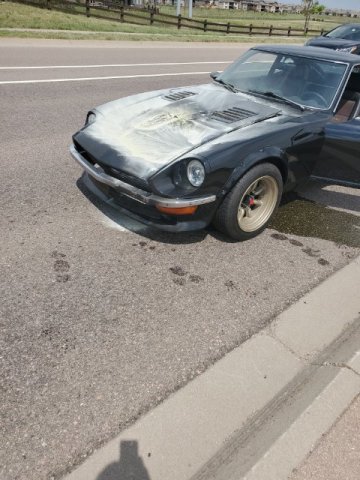
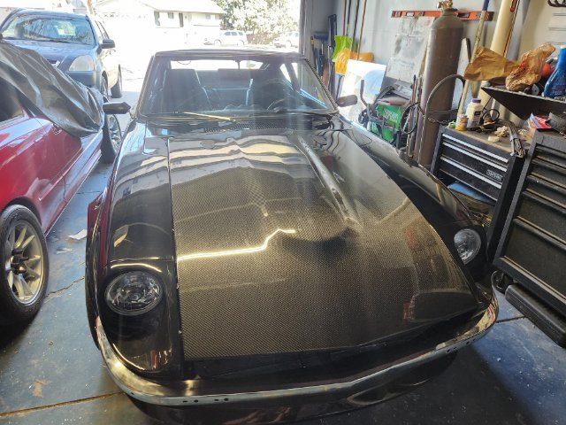
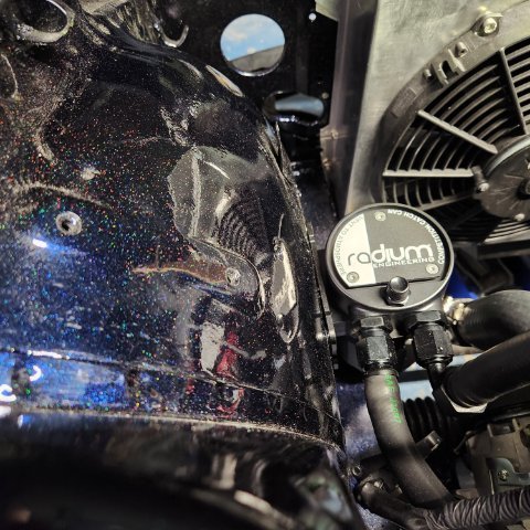
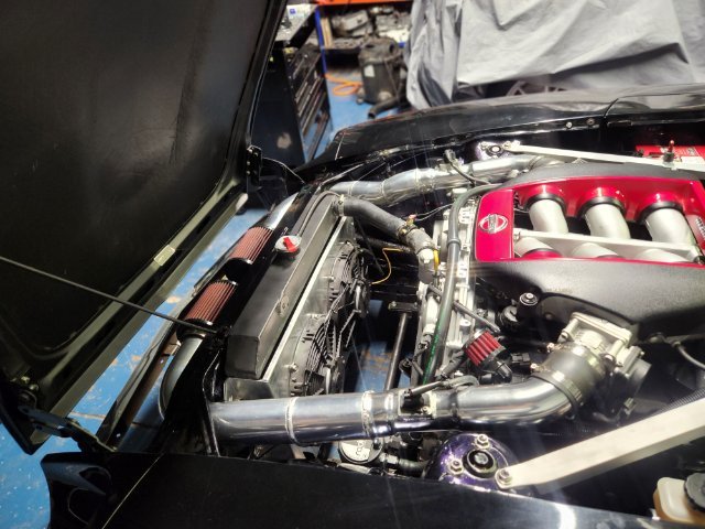
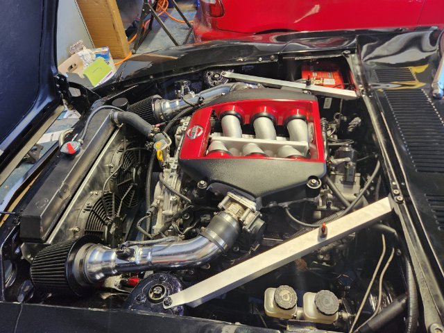
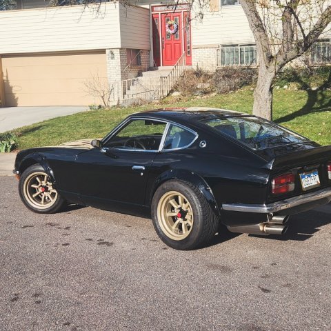
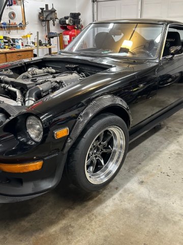
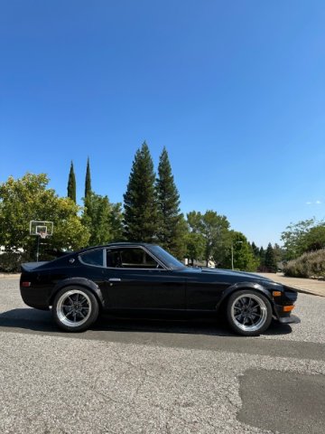
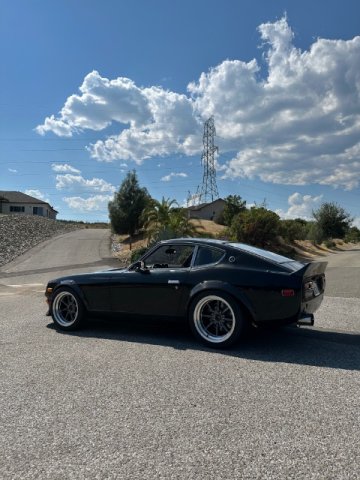
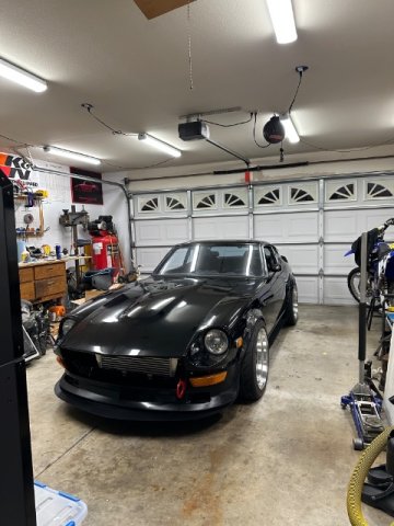
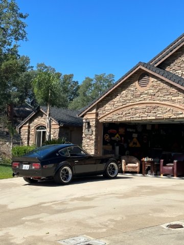
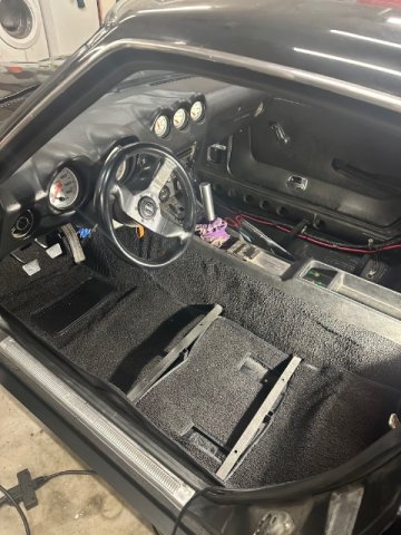
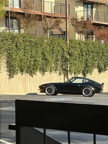
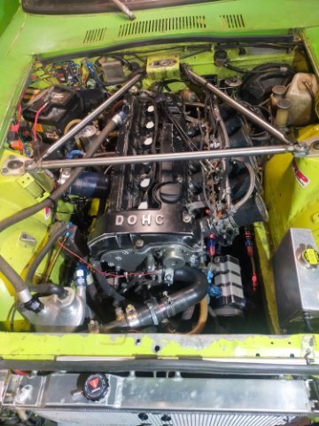
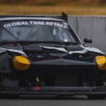
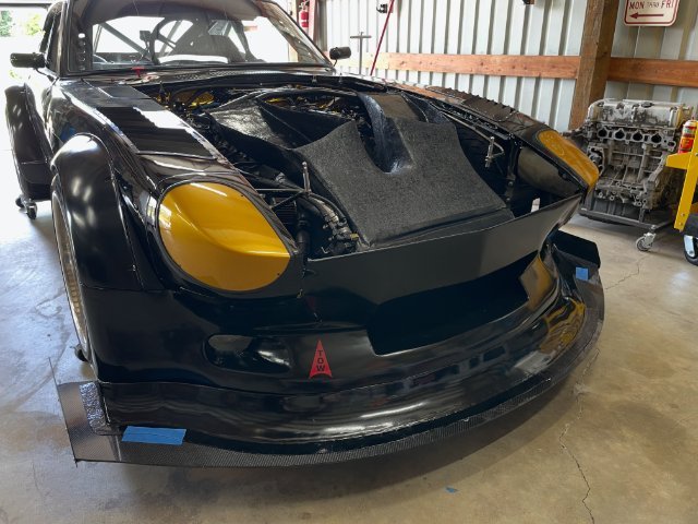
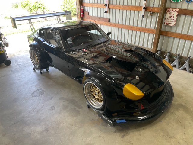
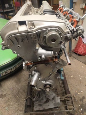
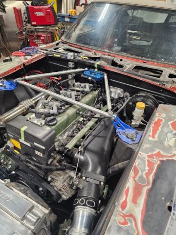
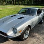
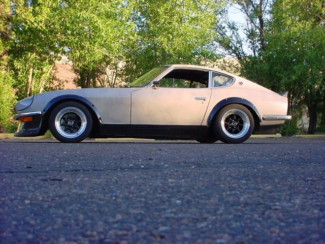
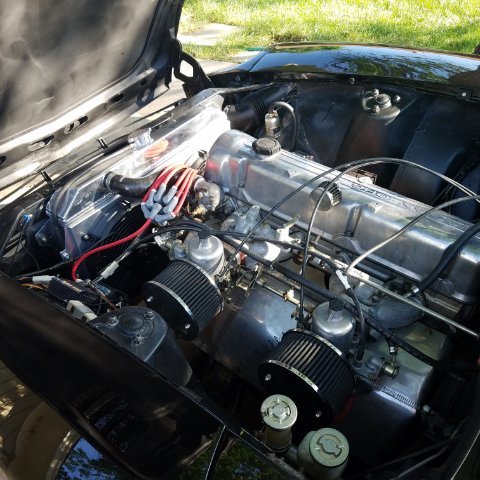
Hi everyone, I am at a good point with my build and wanted to share its history since its one of the few running and driving VQ37 swapped Zs in the country. I am going on over a decade of ownership. I originally bought the car from New Mexico and brought it over to Colorado. Come to find out, it was once a Colorado car also. I picked it up in primer with a rebuilt engine but not really knowing too much about it since all I had were photos and the owners word. The previous owner used it for autocross. The entire interior was missing and it had a rats nest for wiring. I remember it had a switch to manually turn on the fans. It also had a full radiator support and driver side frame rail replacement from a donor Z. I got lucky that this was done really well, I have had no problems getting the car aligned over the years and it drives straight! I saved some money and got the car painted in black, the car was originally a yellow car. The painter actually welded in floor boards and frame rails and closed up the wheel wells from where they were cut for the ZG flares. The rear hatch had to get replaced since it had an inch of bondo over the key hole. Luckily, I was able to track a hatch from a 240Z in the junk yard (when is the last time you have seen that haha). I added sound deadner to the interior and then took the car to an upholstery shop to get the interior put it. I also added some nice gauges. I was able to source some cheap Watanabe 16 inch wheels from yahoo auction Japan. They were different colors but I ended up paying around 900 usd after air shipping them spent another 300 getting them powder coated. I also picked up my Recaro seats from Japan. To this day I have no idea what car they came from but they are one of my favorite parts of the car. The SUs where swapped out for a triple Mikuni 44s. I drove with those and even had them tuned but they were too finnicky at altitude. During this time I got into flipping carbs for resale. I didn't want to deal with the Mikunis and decided to swap to fuel injection. I ended going Jenvey ITBs on Haltech. This setup actually worked great for about a year and even made it to the main page of my local Cars and Coffee. Around that summer I started to develop some running problems where I was running too rich. On my way to the tuner the worst thing happened. The car caught fire. From what I could tell, the itbs backfired and caught the fuel line on fire. If anyone is running itbs on an L Series, I highly recommend an airbox. I got really lucky since a guy like 2 cars back behind me had a fire extinguisher and that the radiator hose blew and stopped the fire. I sent the car over to my tuner/builder and waited on my insurance adjuster to visit the car. I was able to get a full payout through Hagerty and that kickstarted the funds to get my Z back on the road again. I knew I was done with L series. I never really wanted to build something that close to race car since I mostly drive my Z on the streets and occasional canyons. I wanted to stick something Nissan that could remain relatively stock. Something I could start up and just drive. In the past I almost swapped VQ35HR motor and have always had that build in the back on my mind but I noticed that the engines were almost the same price as the bigger brother VQ37. So I went with a VQ37 out of an automatic AWD G37. The reason I chose that engine was to avoid 370z's had been driven hard and the auto engines were cheaper with less mileage. The only change to the block that I needed was a lower oil pan from a RWD VQ and its bolts. I sourced a transmission directly from Nissan since at that time it was actually only about 500 dollars more compared to a used transmission. I looked recently and it seems like the transmission have doubled in price since 2021 when I bought mine. Here are the photos of when I got her back. We ended up putting some flake in the engine bay since I grew up loving lowriders. I also installed a GTR intake conversion. It ended up being a bit of a hassle since the custom fuel rail didn't clear the injectors. We had to extend the fuel ports on the fuel rail to make them taller so that it could clear. I added a catch can since the car is set to vent to atmosphere. I pulled the headers and stripped them and cerakoted them also. The custom hood didn't make it out of the fire so I went carbon fiber. Next I ended up getting the intakes extended to the front of the car to make it a true cold air intake. I recently took the Z engine harness apart and reloomed it and fixed one of my turn signals. Come to find out one of the wires was cut off. With the help of Dave Irwin, I was able to track down all of my missing grounds and also why both lights would blink at the same time (bad switch). I had an extra parts turn signal switch which I harvested and was able to get everything to work out. I recently tackled getting my horn to work. I have never got it to work since my entire ownership. The guys at classiczcar forum really helped me trouble shoot it. Come to find out, my only horn didn't work and for some reason my steering rack wasn't grounded. This is pretty much where the car is now. I took her to a local car meet today and I am hoping to just get more seat time with her. If anyone has any questions about the car or the swap feel free to message me.
4 points
-
Thanks for the replies and comments. Time is always an issue, however Im at the age now where my daughter is 26 years old and working full time. Been married 30 years so the wife is obviously understanding of my hobbies. Hopefully continuing to make progress regularily. Hoping more people come back to the forum and participate in the community. Here is a picture of me and my daughter when she was probably 2ish years old, same car Im working on now. I need to get her back in the shop for a new photo - Time flies
4 points
-
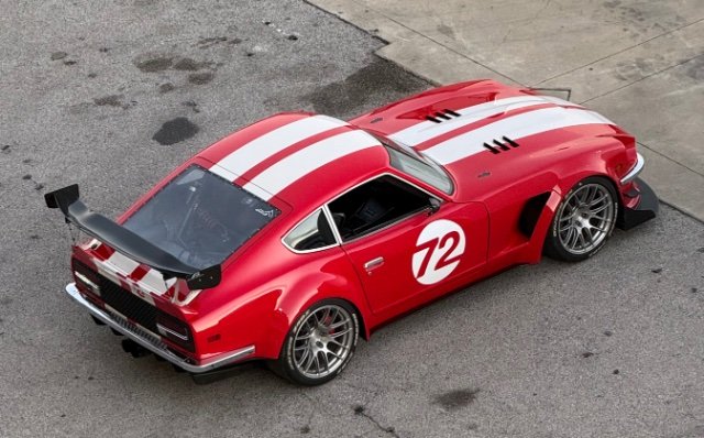
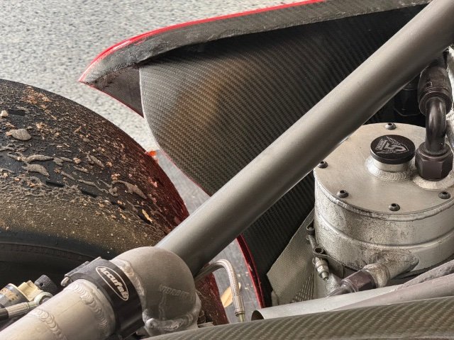
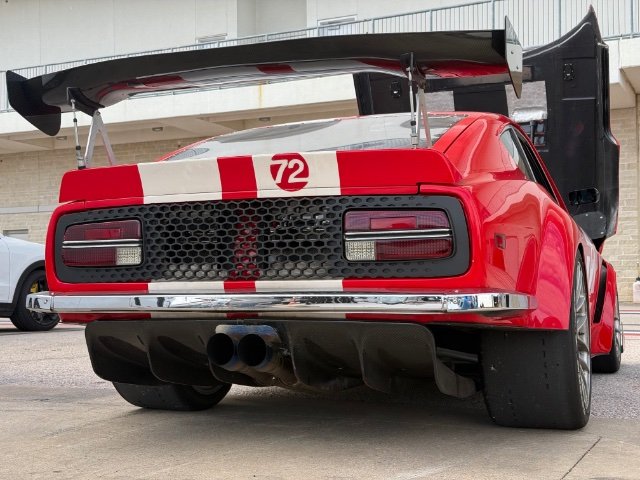
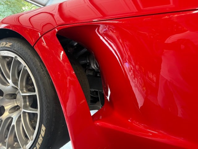
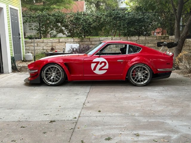
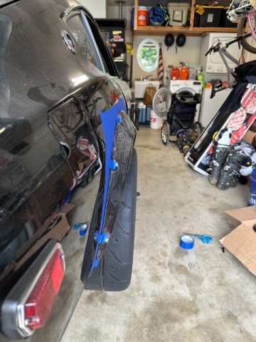
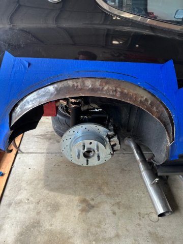
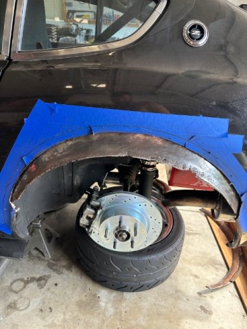
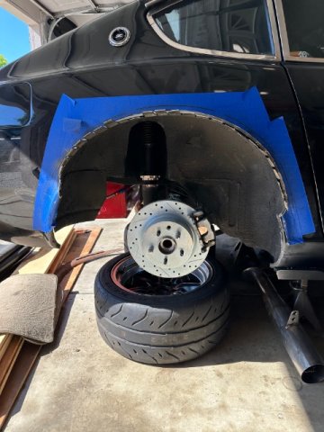
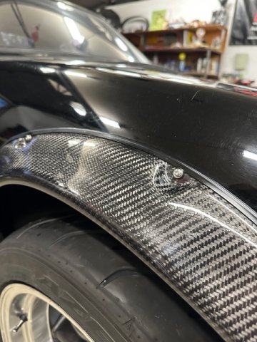
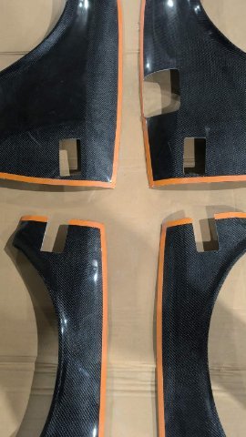
if anyone's still tracking this build I have what might be a last update since the car is mostly done (lol is it ever done?). I finally cad-designed the front fenders and then had a local shop 3D print the parts, then took that to a bodyshop to integrate into the existing fender part and paint it. After that I overlayed the inside walls of it with carbon fiber for added stiffness and protection. I also cut the lower part of the rear fenders and put in a horizontal cf winglet to better extract air. Overall I think it looks great and the resulting new parts helps downforce a ton by extracting air from the wheel wells.
4 points
-
Since that broken rear differential a lot has happened.
4 points
-
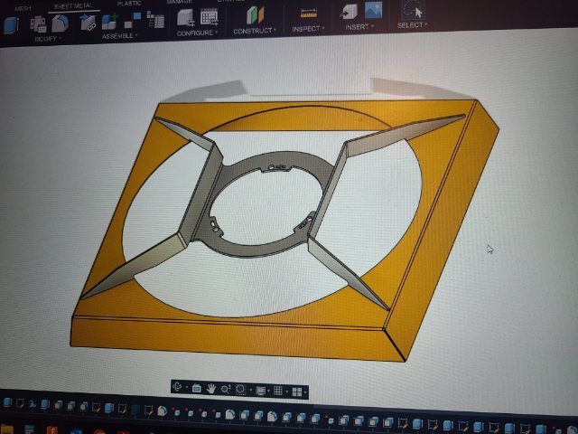
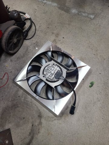
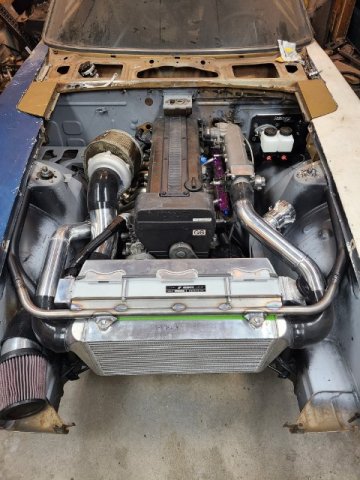
Next order of business was electric fan and shroud, and radiator hoses. I chose the 2016-2019 Camaro single SPAL 18" fan. it will be PWM controlled and is a very popular choice according to the internet as it can flow 5000CFM. Although I cut up the factory shroud to "work" I felt like I needed something fancier. modeled up a base to start working from and had my friends at laserbros in NC laser cut and bend it up. Should have gone one or two AWG thicker so added some bracing as well as some mounts and very happy with the final product. Cut down the radiator and inlets and outlets on the engine and welded on some -16an bungs, made up a couple hoses. in the last photo of the "hose installed" you can see the end of the pipe for the intake I welded into the chassis I mentioned in the previous post. Also decided to move the alternator to the other side of the engine to get it away from the heat. When i pull the engine to paint the bay i'll design and make a bracket to permanently mount it over there.
4 points
-
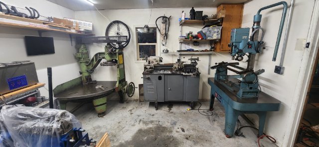
I just wanted to share something pretty exciting in my world. 5 weeks ago I overheard a friend talking about how hard it was to get any machine work done. And it hit me..... I know how to rebuild heads I just need equipment. Did some research and found that 4 of the main shops in the area have sold out or retired. Told the idea to my father in law. And was just spit balling with him. I dont have the cash to start anything and it was just an idea.. well he gave me and my wife a rather large gift and I have now bought a storm vulcan 85b blockmaster and a winona van norman Ph-2000L valve ane seat machine. Still need a valve grinder and obviously tons of tooling. But im excited to see where God takes this. Been 25 years since ive done and work but am excited to get back into it. Plan to get the surfacer going and try to drum up some buisness to make some income to buy more tooling. I onoe they are not the best machines bit they are functional. Just wanted to share
4 points
-
Hi,guys, after one year off with other work, i put back the engine with reground camshafts, and ready for new start !😅 Wait and see ,and Happy new year
4 points
-
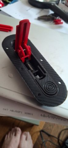
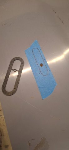
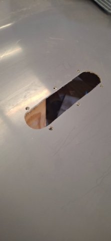
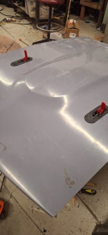
My custom made 3d printed aero hood latches are mounted.
4 points
-
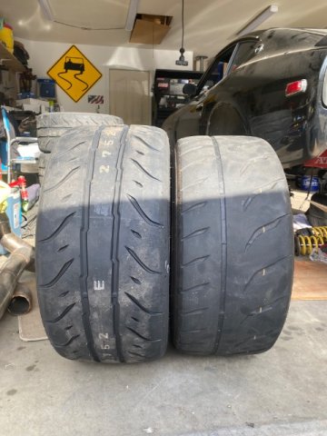
Went out for some Auto-x this weekend, and had a proper blast. Highly recommended for anyone here who still hasn't gone to try it. Enjoy a slow lap, some V8 noises and straight cut gearbox whine. I have a handful of things to think about and address moving forward, but overall I'm very happy with where this sits. Next up is OnGrid at the Ridge in late July for more testing, and maybe, just maaaaybe a little redemption.4 points
-
Good progress over the long weekend. Paint, bondo and fiberglass is mostly a waiting game which is pretty annoying. Got the duct glued together and painted so it looks like something. Trimmed it up a little and we are in great shape! The holes in the hood are a little bit large, but that's ok, and will likely get solved with a new hood (fiberglass) or something on top. Also got the transition piece painted which is exciting! This will help blend the splitter into the air dam, and will get taped onto the splitter once I put some trim on top of it. Need to get to work on the new intake pipe as well, going to put the filter over near the wheel for now. In the future, I'll flip the manifold and pull air from the cowl/wiper box area, but that's a bigger lift in terms of fabrication. Can't tell you how excited I am to have a metal fabrication project after 10 months of composites.
4 points
-
Meh, he's a paid supporter of the site. I figured I'll give him his moneys worth4 points
-
I started typing a number of snarky responses and have settled on Wow what a shitty thing to say.4 points
-
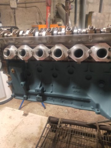
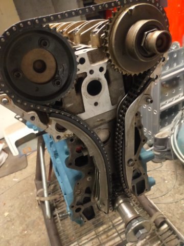
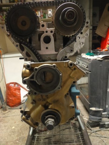
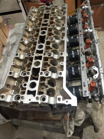
well old story , but MAG58 was right, mercedes M104 head is possible on a datsun L28 stroked , build is not over but we will see what happens soon bye bye Didier
4 points
-
**UPDATE Went to court yesterday and basically played dumb. Told the judge that "I went to the state ref and he told me since the car is so old that he couldn't do anything to certify it. So how do I go about taking car of this ticket. The vehicle is a pre smog vehicle so I've never had to SMOG it" The judge said "Ok so what Im going to do here is dismiss the case cuz it seems like your car doesn't qualify for an inspection. Sorry about the inconvenience Mr. Soto" I tried to play it cool but I was so happy. After reading all the horror stories from other people about having to revert to stock and all that I was lucky I guess Hope this thread helps someone going through something similar4 points
-
Greetings Everyone, Due to the increase in spammers HybridZ, registration has changed from being automatic to manual. That means one of the Admins will need to approve any new registrants. If you ask or tell someone about HybridZ (please do) let them know registration isn't automatic anymore. We'll do our best to stay on top of any additions and hopefully you all will see a lot less spam. Thanks, The HybridZ moderation team4 points
-
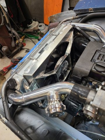
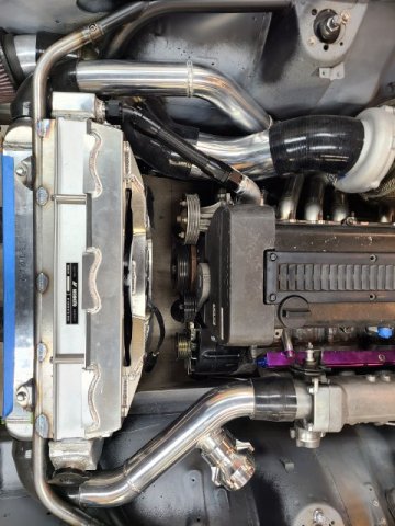
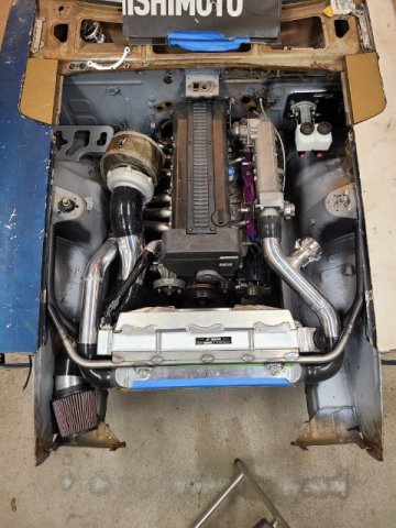
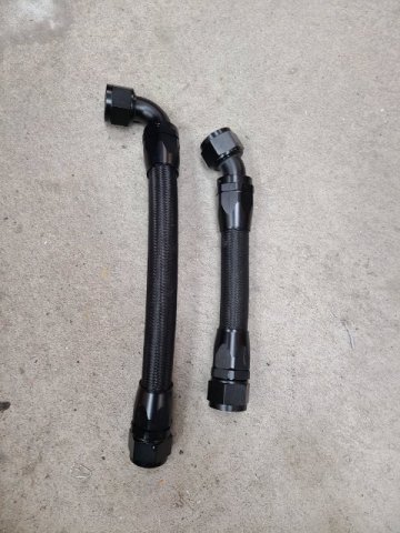
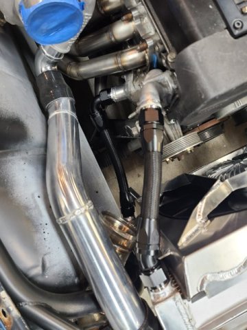
Love the way this is coming out. its been a challenging balance to thread between making everything neat and tidy and making sure I remember its a race car and needs to be functional. decided to polish the intake manifold and turbo, which looks great but upkeep is gonna be a challenge. exhaust is mostly done and welded. need to make a fancy tip for the back. wrapped the downpipe and mid pipe. need to pull the manifold and wrap that too. originally made a open dump wastegate but then changed it up to recirc it because we have a couple tracks with some noise restrictions. I'll order another v band and wastegate outlet so i can cap the exhaust and run it open if the track doesn't have a dB restriction. Fuel system is done. bulkheaded thru the floor. 3d printed some mounts and have it mounted along the floor. injectors are in. got most of the turbo lines made up. opted for the turbosmart oil pressure regulator for the turbo. i've never dealt with a turbo this small and man its a challenge to fit everything. drain is really tight. hits v band and clamp but think i may have the puzzle solved to make it work. fuel fill is welded up. went with stainless to mitigate the risk of corrosion with ethanol.
3 points
-
Was not implying that the only way to get work done on a project is to not have a wife and daughter!!! I can see how that could have come across. Mine is 14 and will be a freshman this year. Ive got 4 years..... Then who knows. As she has gotten older I've been telling the stories of her helping me in the shop when she was little. Her stepping into a drain pan full of oil in ugg boots that I promptly threw away with out telling mom, Me hearing a pppsshhhh noise and I turn around to see her with a my blow torch pointed at her face, Praise the Lord she didnt click the igniter She would have been around 2 also at those times.3 points
-
Been spending alot of time getting the chassis on the NA car cleaned up and ready for paint. Its a super clean almost a no rust car, so I want to strip it completly bare, metal prep it, straighten the floor pans which are really clean just slightly dented from wrong jack points. I started out by stripping everthing off and making digitized and CAD files of all the tar flooring. You can still buy it from Nissan. I have a laser cuttter so I will use it to cut all the replacements. It is an original paint car, so it was hard going in on it. Next I put it on my rotissary I built for the Turbo car and got to work on stripping all the factory undercoating. Using a heat gun, scraper and some mineral spirits did the trick but it took a long time. All super clean original metal under the car This is what it looked like under the front fenders BEFORE cleaning, so super happy and even under the cowl all original paint
3 points
-
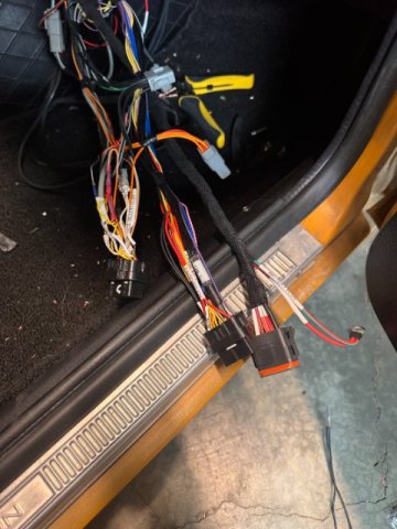
Almost got it done. Such a pain in the as* I probably should have started over, from my old ecu to this ecu wiring.
3 points
-
Hi everybody, long time for updates. Been quite busy with kids and a very nasty divorce going on. The good news is my garage and cars are still intact and I am still making progress, although very slowly. Car is very close to track testing. I decided to have a new pair of steering arms machined to match the front geometry. I will post more when they are finished. In the interim, I took the time to catch up on some side projects I wanted to do. With the advancement of AI, some of the projects I considered impossible a couple years ago have turned out to be quite easy now and very inexpensive. Based on Arduino technology, I have integrated a motion sensor into my data acquisition system. I use a Race Technology DL1 Club box which is limited to 8 analog sensor inputs, but can decode an almost unlimited amount of CAN signals. So I built a circuit that decodes the motion sensor and outputs a CAN signal. I now have 3-axis roll, pitch, and yaw angles along with speeds and acceleration live data. It will all be packaged in a small box that mounts in the car. Next is a infrared tire temperature monitor. A 16x4 temperature array sensor once again combined with Arduino and CAN output board. I am trying to package this as small as possible so it can be mounted on brackets roughly 4" above the tire. Again real time data of inner, middle, and outer tire temps while driving. Hopefully saves a lot of time when dialing in the camber and pressures. More to come...........3 points
-
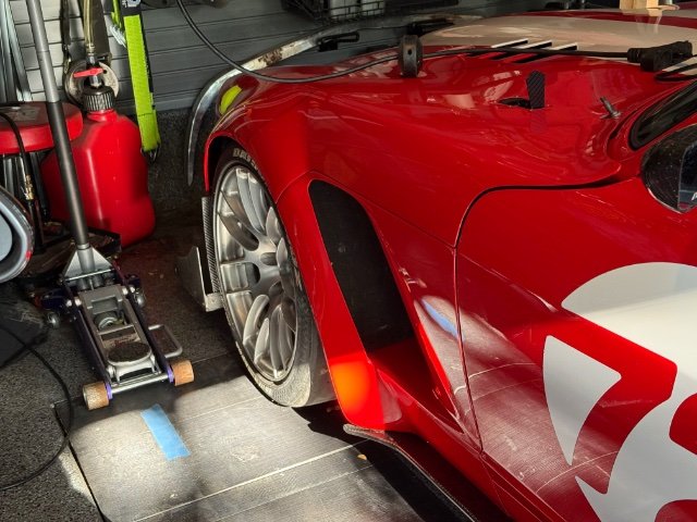
Without the oil cooler, my water temps were never an issue. Never over 200 on track. When I put the Aviaid Mangusta pan on the car it had a provision for an oil temperature sender. Even though my water temps never got too hot on track, once I installed an oil temp gauge, I discovered that my oil temps were getting near 300F. I added the Setrab 34 row cooler, and my oil temps stay below 250F.3 points
-
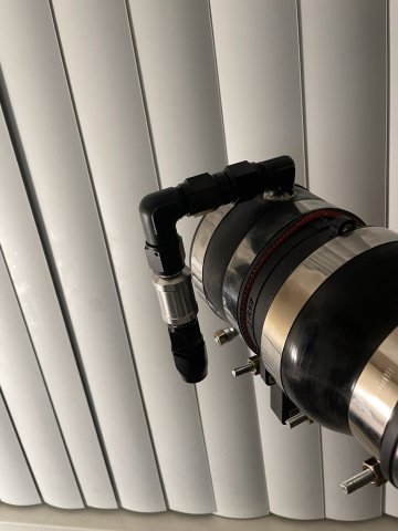
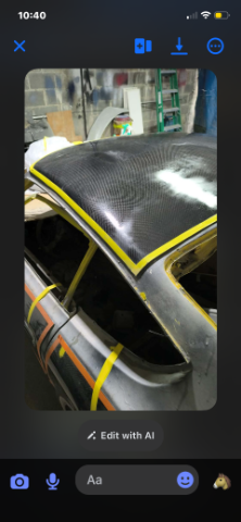
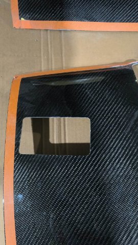
03-25-2026 ATLAS Z UPDATE: I got some of the fittings in I need for my crankcase pressure to catch can to intake setup. Also tall of my carbon fiber panels have been cut, final polishing on roof section then ready to ship to me and bond them on! Then make the borders shiny!
3 points
-
3 points
-
Unrelated update but reasons as to why there's been a lack of updates to this thread: Got a new job that demands a lot more of my time so unfortunately less time to optimize the SLA conversion. Upside however is that I'm learning NX which seems to be some next level software. I think this design is going to take one more fundamental change to really get the dynamic geometries perfect but the work I have so far has been a pretty excellent starting point. The car is also back from the rust repair shop and the cage shop, needless to say my wallet is in a lot of pain at the moment (especially with the S54 being built) but we do these things not because they are easy but because they are hard and we hate money. Anyway, enjoy some photos of the cage in the meantime.
3 points
-
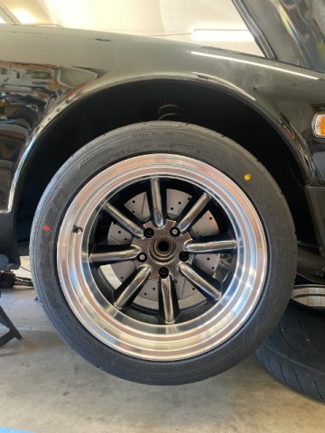
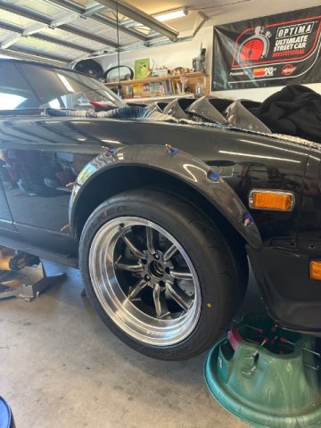
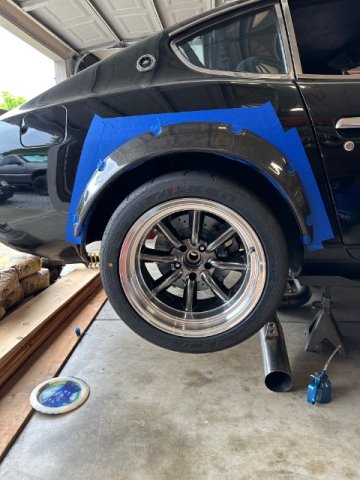
Hi All! I've owned a few s30's in the past and finally decided to build one. My car background is a lot of JDM cars including Supra's, AE86s, S13s, Skylines, a Stagea 260rs, etc. I have always loved the style of the s30 (don't we all), the aftermarket support for it and the random people who would stop me and tell me about their "Z" story. The story of this build started over a year ago when I purchased this 1978 Datsun 280z. The story behind the car (that I know of) was it is an American car that was brought to Washington and held at a speed shop awaiting restoration. Then was bought and stored in a heated warehouse for years in BC before i bought it. A little side story, I originally purchased a 1971 240z from the same person and they also had the 280z for sale but was well out of my price range. I would have loved to restore the 240z but unfortunately the amount of work it needed was well beyond my budget and experience just to get it to a useable condition. If you looked at it funny, rust would fall off the car. Mistakes we made. I was sold on what it could be but not what it will take to get there. almost a year later the 280z was still for sale, and the price was a little better. With some luck, i was able to convince the owner to trade back the 240z and cash for the 280z. Success!...Now, it seems the 280z was re-sprayed a British racing green but wasn't done the best and was flaking so i believe that's why it originally underwent the restoration in Washington. The car was just a rolling chassis, the front end had been primer epoxy'd and luckily had everything in boxes and labeled like "driver door guts", or "Rear hatch slam", which was nice to see. Now the goal of this project was to be a fun drivers, resto-mod car. It will be getting an RB26 from an r33 GTR, an RB25 transmission, DBW for the factory ITB's, Techno Toy Tuning full suspension, brakes, differential swap kit, running a Haltech S3 ECU and Wiring Specialties Harness, Poly fuel tank with an r32 skyline Radium hanger and Hellcat fuel pump. The bigger ticket items like turbo/manifold, radiator/fans, and then some smaller things are missing but most of the project is there now. I do plan of re-wiring the whole car considering I'm spending money in every other area. Now, just like anyone, I did set out with budget but considering since I last built a car, prices have gone up for parts which I stupidly didn't account for. Also a lot of, "well if i'm already doing this, then i might as well do that", and "since i have this off, i might as well get that." So the budget has been blown....but at least I'm happy! (maybe). BUT as it stands, the suspension and diff swap kit is in and the car is currently at the body shop getting the sunroof hole patched as well as some of the smaller trim holes plugged and a few small rust spots taken care of. Here are some pics throughout the build and as it stands. Any questions, advice or help for some "gotchas" will be welcome!3 points
-
Great work so far! I’m sure this will be an awesome build. I suspect you will be running fender flares or a wide body kit seeing as your wheels are poking out a bit?3 points
-
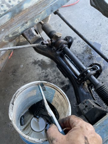
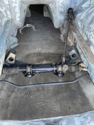
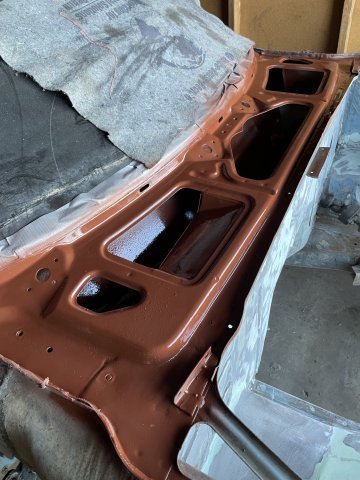
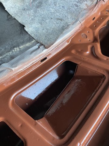
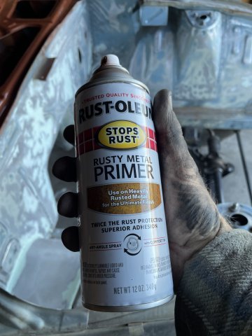
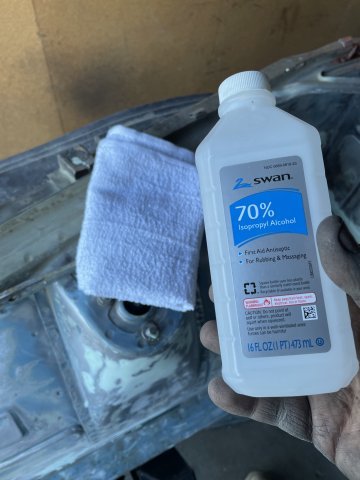
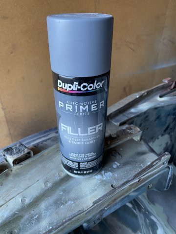
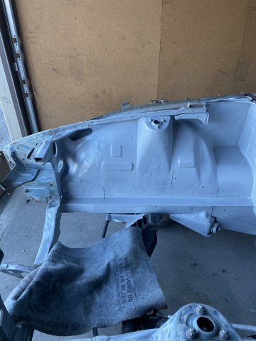
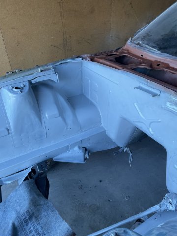
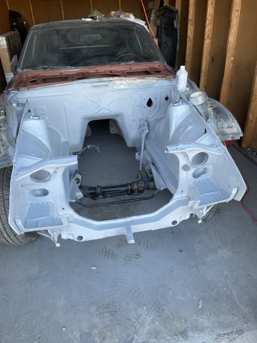
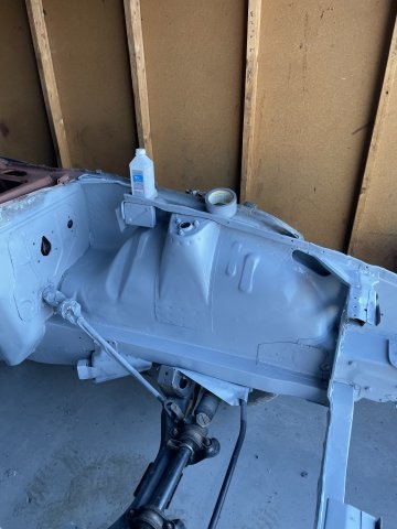
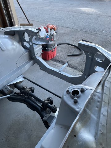
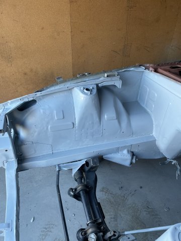
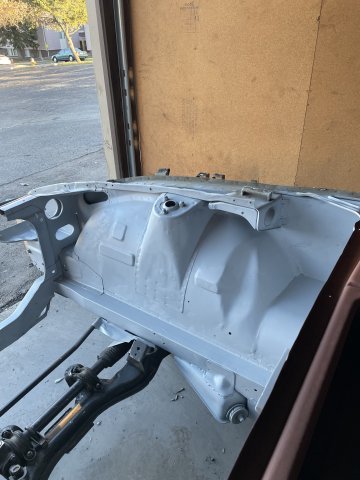
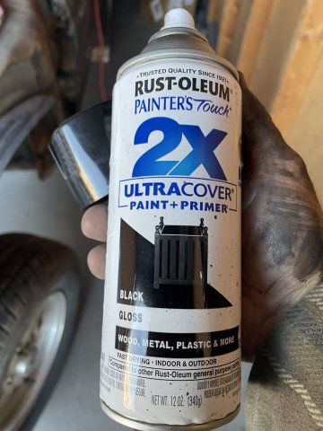
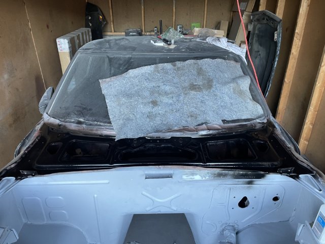
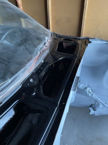
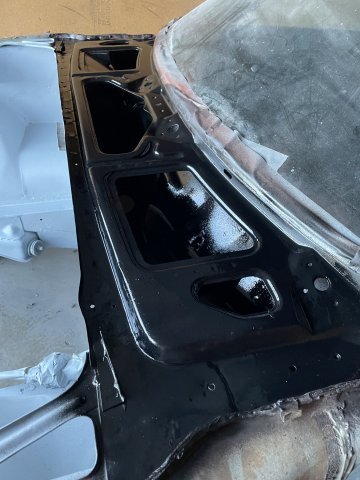
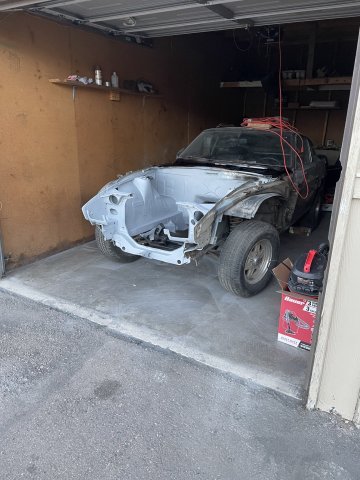
11-01-2025. 260Z work. I got the engine compartment sanded down after the glaze and then cleaned up the crossmember and rack with cleaning solution "g@s" and a toothbrush, and then steel wool, etc. Then I vacuumed out the cowl and primed it with rustoleum rust primerand top coated it with gloss black paint, then painted the engine bay with filler primer. Once dry I will use some spot putty I picked up on the areas that need it, hand sand it smooth and filler primer over that. Once it is good, then I will progress to color and then clear. Busy day! Pics:
3 points
-
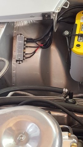
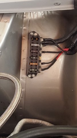
Picked this up from local hot rod shop for my 240z SBC 350 project about 13 years ago. Circuits: Electric fan relay Fuel pump Radio and amplifier Power windows Summit Racing/parts store etc probably have this fuse box.
3 points
-
Got the sensor figured out. It is idling around 130-140 F. Should be OK. I have to post a video. Sorry but I think this thing sounds bad ass. I have an insert in the exhaust so I dont need earplugs.3 points
-
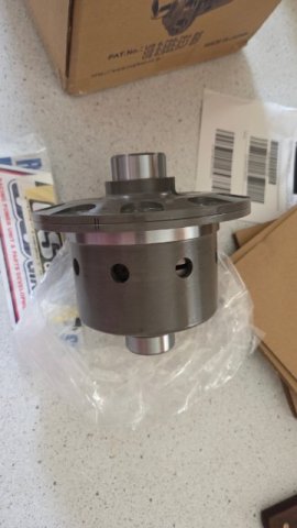
It was a good idea not to wait on rebuilding the 3.54 diff. The new LSD arrived weeks after I expected it and there's no shot I would have been able to swap it into the spare R200 before my trip. I'm excited to get this together in the winter though!
3 points
-
Some of their stuff is good and some is hot garbage. Max the owner doesn't stand behind his product and has a tendency to try and blame "modifications" to your car as the reason. I have a lengthly (4 page) post on classic z car about my problems with his door assemblies. Resurrected Classics door problems I have their door weather strips and their fuel filler neck and the are excellent. My advice is no matter what you buy test fit as soon as it arrives and go from there. The doors were so bad that I ended up not using them. Max refuses to refund my money so I make sure to take the time to tell people about my experience. Do not trust what he says as he says whatever he needs to to get out of doing the right thing. Caveat Emptor with this guy for sure.3 points
-
For a street car I think the rails make sense. For a race car that has a cage perhaps not. For a similar amount of weight you can triangulate the cage with tubing on top of the floor that extends to the suspension pickup points.3 points
-
New to the forum but I wanted to make a summary of my build status/plans for my 1982 280zx. I got the car with 150k miles 7 years ago in a straight up trade for a Kawasaki Ninja 250 (crazy, I know). I was in high school/college for most of that time so my major upgrades had to wait until I got my own garage 2 years ago. Overall goal is an aggressive (~350hp) restomod that I can take to the track occasionally. I've been recording my build progress but only recently went back to edit/upload all of the videos. If you're interested in following along, subscribe to my YouTube! I'll be posting videos every 2 weeks until I'm all caught up on footage. https://www.youtube.com/@engiandesign 2018 (One year after I got the car) January 2023 Engine Bay April 2024 Engine Bay Stripped, and Painted May 2024 Engine Rebuilt July 2024 Engine Bay Mostly Complete Current Mods: Fully rebuilt L28ET Rings, bearings, studs Stock internals Valve job with new valves and seals Cometic MLS head gasket Cam sprocket and timing chain Port and polished head High volume oil pump Schneider stage 2 cam regrind with matching springs, retainers, lash pads and resurfaced rockers Ported exhaust manifold with custom external wastegate piping Tial MVS 38mm wastegate Borg warner S257 SX-e T4 7670 CXRacing Intercooler Kit Mishimoto 25 row oil cooler Mishimoto catch can Champion 3 core radiator FF Dynamics dual electric cooling fans 3.5" cold air intake 240sx 50mm throttle body Aeromotive fuel pressure regulator Upgraded 100 Amp alternator Pallnet fuel rail 1000cc Bosch EV6 injectors Megasquirt MS3x kit from Godzilla Raceworks TSP high flow fuel pump All new glowshift gauges (9 total) CXRacing 3" stainless exhaust modified with X-Force Varex valved muffler Front/rear sway bars 280z style aftermarket air dam Louvers New carpet 4 Infinity 6x9 midrange speakers with 10" Pioneer sub Future Mods Multi-spark ignition CD009 transmission swap Wilwood big brake kit Custom front grill Side skirts Rear diffuser Duck bill spoiler Fender flares Coilovers Rims/tires Seats I'm sure I'm forgetting something on this list but that's pretty much everything. I got it running in July and after a few months of dialing everything in, its finally running great! I'm currently running 9lb of boost on a very conservative tune but it still rips. Luckily my work has a chassis dyno and some very experienced tuners which should help unlock a lot more power. This winter I plan to focus on body work/aesthetics along with rims/tires/suspension. This is my first project car so I welcome any feedback or suggestions, especially related to future mods. Make sure to subscribe to my YouTube for more updates!3 points
-
Before removing the diff, I would check the u-joints on your driveshaft as well.3 points
-
Bumping zboi's thread so he can continue his contributions to the community. Let's see an update.3 points
-
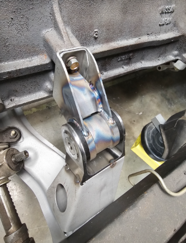
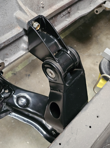
I finished up the front crossmember and motor mounts Started with a stock crossmember with the need for new engine mounting since I moved the engine in the chassis back about 1 inch. I extended and boxed in the existing upright Some grinding and blasting to clean it up 3 D printed mockup of a machined bracket I made to accept the moustache bar busings. I designed these years ago and have been in the NA car for 15 years. Worked well I machined this weld in bracket out of a solid chunk of steel because I wanted the details for the bolt holes and you could not do that with bent sheet metal. Stupid but fun. More soon
3 points
-
That makes all domestic orders shipped! One international to figure out still. Thanks again for everyone's patience while I got through these. I didn't anticipate it to take 6 months! Final tally on the donation amount to come as soon as I tally things up, but it will be over $1k. Funds have been flowing to Dan as needed over the last 6 months 1. 7d2jz 2. MAG58 - PAID - SHIPPED 3. MAG58 - PAID- SHIPPED 4. Crespo79 - PAID- SHIPPED 5. Jeffrox - PAID- SHIPPED 6. jhm - PAID- SHIPPED 7. onthego- - PAID- SHIPPED 8. onthego- - PAID- SHIPPED 9. pepper - PAID- SHIPPED 10. pepper - PAID- SHIPPED 11. ModernS30 - PAID- SHIPPED 12. Masonvonritchie - PAID- SHIPPED 13. rxx2rxx2 - PAID- SHIPPED 14. rxx2rxx2 - PAID- SHIPPED 15. Sonethirty - PAID- SHIPPED 16. S30TRBO - PAID- SHIPPED 17. S30TRBO - PAID- SHIPPED 18. Kennysgreen280zt - PAID- SHIPPED 19. Kennysgreen280zt - PAID- SHIPPED 20. Kennysgreen280zt - PAID- SHIPPED 21. ElliottOhZ - PAID- SHIPPED 22. Oki570Z - PAID- SHIPPED 23. lowrider - PAID- SHIPPED 24. lowrider - PAID- SHIPPED 25. lowrider - PAID- SHIPPED 26. jnjdragracing - PAID- SHIPPED 27. jnjdragracing - PAID- SHIPPED 28. OldAndyAndTheSea - PAID- SHIPPED 29. OldAndyAndTheSea - PAID- SHIPPED 30. JonRHD - PAID- SHIPPED 31. JonRHD - PAID- SHIPPED 32. 75280z - PAID- SHIPPED 33. 75280z - PAID- SHIPPED 34. CalZ - PAID- SHIPPED 35. CalZ - PAID- SHIPPED 36. LanceVance - PAID- SHIPPED 37. LanceVance - PAID- SHIPPED 38. Stunt 39. Stunt 40. _akuma_no_zetto_ - PAID- SHIPPED 41. _akuma_no_zetto_ - PAID- SHIPPED 42. 1 tuff z - PAID- SHIPPED 43. 1 tuff z - PAID- SHIPPED 44. Zlost - PAID- SHIPPED 45. AydinZ71 - PAID- SHIPPED 46. AydinZ71 - PAID- SHIPPED 47. zredbaron - PAID- SHIPPED 48. zredbaron - PAID- SHIPPED 49. zredbaron - PAID- SHIPPED 50. airbrush-ed 51. Chris Damato (FB) - PAID- SHIPPED 52. Chris Damato (FB) - PAID- SHIPPED 53. evildky - PAID- SHIPPED 54. torqen2k1 - PAID- SHIPPED 55. torqen2k1 - PAID- SHIPPED 56. torqen2k1 - PAID- SHIPPED 57. torqen2k1 - PAID- SHIPPED 58. torqen2k1 - PAID- SHIPPED 59. torqen2k1 - PAID- SHIPPED 60. Mayolives - PAID- SHIPPED 61. Mayolives - PAID- SHIPPED 62. Mayolives - PAID- SHIPPED 63. bkz72 - PAID- SHIPPED 64. Wizzurp - PAID- SHIPPED 65. Wizzurp - PAID- SHIPPED 66. Leon - PAID- SHIPPED 67. Gollum - PAID- SHIPPED 68. Gollum - PAID- SHIPPED 69. Gollum - PAID- SHIPPED 70. AB240z - PAID- SHIPPED 71. AB240z - PAID- SHIPPED 72. AB240z - PAID- SHIPPED 73. AB240z - PAID- SHIPPED 74. AB240z - PAID- SHIPPED 75. AB240z - PAID- SHIPPED 76. AB240z - PAID- SHIPPED 77. AB240z - PAID- SHIPPED 78. AB240z - PAID- SHIPPED 79. Zetsaz - PAID- SHIPPED 80. Zetsaz - PAID- SHIPPED 81. Zetsaz - PAID- SHIPPED 82. Wedge 83. 24Oz - PAID 84. ihavearustedz - PAID- SHIPPED 85. clarkspeed - PAID- SHIPPED 86. niner11 - PAID- SHIPPED 87. 1970 240z - PAID- SHIPPED 88. 1970 240z - PAID- SHIPPED 89. 1970 240z - PAID- SHIPPED 90. 1970 240z - PAID- SHIPPED3 points
-
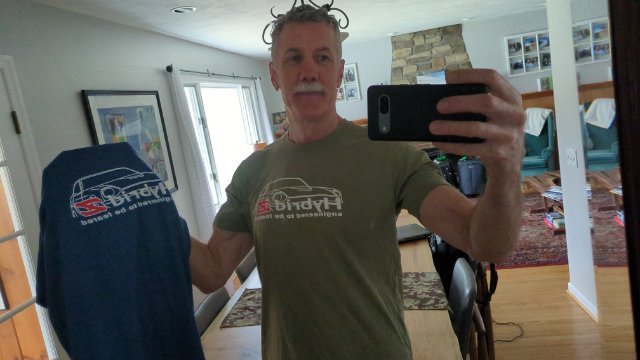
My shirts arrived today, with the wait - huge thanks to Ryan for tackling this big job that benefits all of us and HybridZ! It was difficult to choose amongst all of the colors but very happy with my choices!
3 points
-
I really wish things would swing back towards the forums. I can't tell you how many times I know the answer to or could add to a post on FB but I don't since it really has no longevity. I always felt like I was adding to the overall knowledge base when I posted here. I can go on and on but I really hate it.3 points
-
First start up since starting the restoration. Kind of shocked she started right up on the first go. Was expecting something on the MegaJolt to need fixing, but it worked great. Went with Magnacor wires, but they made a mistake and did not fit them up with the right coil boots. Being remade and shipped, so I am using 05’ ford explorer NGK wires for now. Went with a “7” heat NGK plug on account of the 10:1 CR. It’s raining this weekend, but just need to dial-in some crude alignment and she will be road worthy IMG_2339.mov3 points
-
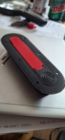
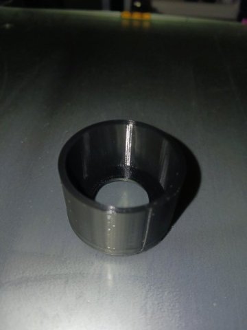
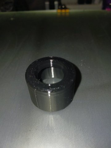
So this is the finished product if anyone else is interested. It is made out TPU which is very flexible (and hard to print). I have used TPU to create plugs for my floors, wiring grommets and other such.
3 points
-
Just wanted to say again a HUGE "Thank You" to @cockerstar for doing this (a FIFTH time)!!!! Really appreciate all his time and effort to make this happen. You da' man, Ryan!!! 👍👍3 points
-
an LS is also vastly more expensive then a traditional 350 swap. He should do whatever he wants to do.3 points


.JPG.610ed984fe518681d3e91e1e9db2c217.JPG)
.JPG.e329303b2289e41a95dd4a5e6b9b2bf6.JPG)
.JPG.9c7a1ba75f1d864dfbf8d25cacd45f1e.JPG)
.jpg.9a495c827ef23eaabc1d5953ebb2a222.jpg)
.jpg.a28119b0a846d3cc307ea2f488edf719.jpg)
.jpg.9342f7c8ede52da0e23921e7d8cf589c.jpg)